-
- Actuators
- Coil Design
- Electromagnetic Brakes & Clutches
- Inductors
- Levitators
- MRI
- Motors
- Alternators and Generators
- Electromagnetic Brakes and Clutches
- Sensors
- Loudspeakers
- Magnetic Encoding
- Relays and Contactors
- Solenoids
- Shielding
- Electromagnets
- Magnetic Bearings
- Magnetic Signatures
- Magnetic Fixtures
- Magnets
- Non Destructive Testing
- Particles
-
- Antenna Radiation Characteristics
- Simulation of an Airplane
- EM Simulation of a Desktop
- EM Compatability and EM Interference
- Cable Junctions and Terminations
- Filters
- Lightning Strikes
- Microwave Circuits
- Microwave Ovens
- MRI
- Near Field Analysis
- Radar Cross Sections
- Radio Frequency Cavities
- Reflector Antennas
- Sensors
- Ultra Wideband Antennas
- Waveguides
- Antennas
Antenna Design
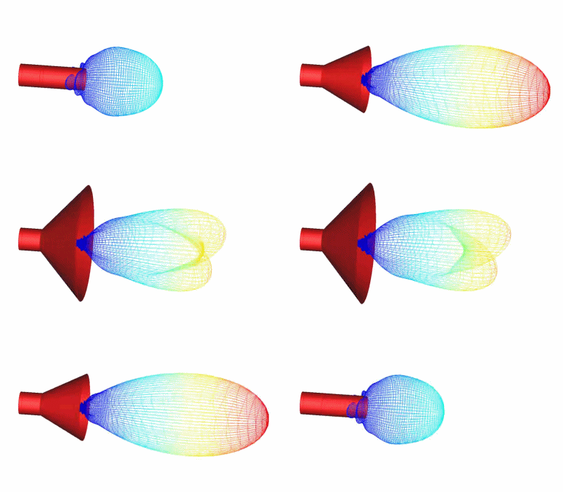
Antennas are normally modeled with CHRONOS™ and SINGULA™.
- Linear antennas
- Microstrip antennas
- Horn antennas
- Reflector antennas
- Dielectric resonating antennas
- Phased array antennas
- Slots in waveguide

In the case where the geometry is much smaller than the wavelength, the antenna/receiver is best thought of as inductive coupling. The simulation software to model this with are MAGNETO™ (2D/RS) or AMPERES™ (3D simulation). If there are conductors present which will affect the coupling through Eddy Currents, then use OERSTED™ (2D/RS) or FARADAY™ (3D simulation) instead.


.gif)

